In my first post of this month, 15th January, I mentioned that I had recently installed a new alternator and electronic ignition kit to my bike.
Today I look more closely at how we accomplished that task.
I wrote and first published this article for the Toolbox on the Chang Jiang Unlimited web site.
I decided to “Get a Little Help From My Friends” (to quote a Beatles tune we used to sing along with a few decades ago) and rode my bike around to Brian Harmsworth’s place a few kilometres from my home.There we removed all the old components and fitted the new kit and took enough photos to write up and publish a pretty good “how to do it” manual.
- We first removed the negative earth wire from the battery terminal.
- We drained and removed the fuel tank.
- We removed the front crankcase cover.
- We removed all wires from the alternator.
- We removed the rotor bolt which fastens the rotor to the front of the crankshaft
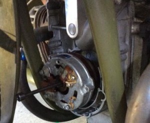
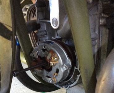
In this photo we see the allen-headed rotor bolt almost fully removed from the front of the crankshaft and the alternator. - We removed the old stator unit.

Here we see the old stator being lifted off while the rotor remains in place on the front of the crankshaft. - We removed the old rotor leaving the front of the motor looking kind of empty.
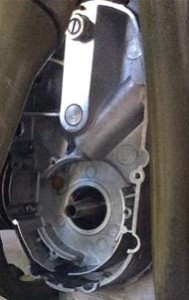
Here the complete original alternator has been removed from the front of the crankcase. - We fitted the new stator unit

We fitted the new stator unit with the sender unit in about a two-o’clock position. - We ensured that the pistons were at TDC (Top Dead Centre)

We removed the spark plugs and used the kick starter to turn the engine until the “0” Zero mark on the flywheel was clearly visible through the peephole near the left carby, thus ensuring that the engine was exactly at TDC (Top Dead Centre). - We fitted the new rotor and lined up the timing marks.

We fitted the new rotor and carefully lined up the painted marks on the rotor and sender so that the ignition timing would be perfect and then tightened up the bolt which fastens the rotor to the crankshaft. There are a lot of steps here which are fully explained in the manual I wrote. - We removed the air cleaner and the plastic electrical box.

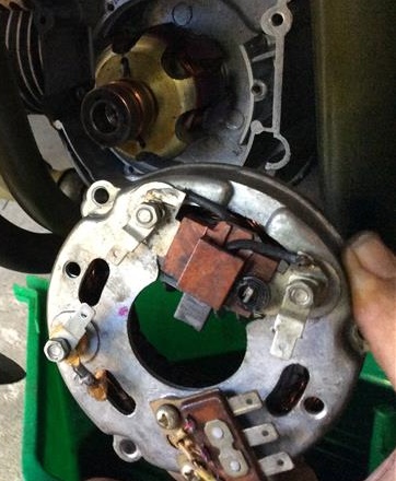
We next removed the air cleaner and the plastic housing around the various electrical bits. - This photo shows the original electrical components:

Here we see the starter solenoid (relay), the voltage regulator and the rectifier (diode board). - We removed the unwanted electrical parts:

We removed all attached cables and then removed the voltage regulator and the rectifier. The old wiring loom parts were discarded.

- We fitted the new rectifier in place of the old voltage regulator:

We fitted the new rectifier using the screws from the old voltage regulator. - We made a metal tab to mount the new ignition unit in place of the old rectifier:

While we could easily have fitted the new ignition unit to the components board using plastic cable ties, we decided to make a tab to fit the back of the unit and we pop-riveted the tab to the board. - Everything in place ready to wire up.

We pushed the rubber mounting at the back of the new electronic ignition unit onto our new tab and now everything is ready to wire up. -
On the new wiring loom sections we connected the two-pin connector between the stator and the electronic ignition and the three-pin connector between the stator and the rectifier.
-
The red wire from the electronic ignition unit is fastened to the positive terminal of the coil in addition to the wire that is already on that terminal.
-
The yellow wire from the electronic ignition unit is fastened to the negative terminal of the coil in place of the old wire from the points (distributor).
-
The red wire from the rectifier is connected to the left upper terminal of the starter solenoid which is where the positive wire from the battery is also connected.
-
The blue-white wire from the rectifier is connected to the wire in the old wiring loom which goes up to the charging indicator light in the headlight shell.
-
The black plastic housing is fitted over the electrical components and the battery is reconnected.
- After checking that the engine could run we tidied up the wiring:

After running the engine for a few seconds using the fuel remaining in the carbies just to check that all is okay, it is time to tidy up the wiring using black plastic insulation tape and cable ties and making loops to take up the slack where the new wiring looms are too long.
- The tank was fitted and filled and the bike was taken for a test ride.
During the test ride a long steep hill which used to always see the bike chugging slowly in first gear was breezed over easily in third and on a short stretch of highway where the bike was normally cruised at 70 km/h I was amazed to see that it was effortlessly cruising at 85 km/h, so the new computer is able to work magic with the ignition timing.
A couple of weeks after fitting the new system, the bike’s engine failed during a mountainous rally ride. It turned out that, because it had been driven consistently much faster than it had ever been ridden before, the petrol tap had vibrated around to a partly closed position which leaned the mixture which overheated the engine causing the petrol in the carbies to boil. Not immediately realising what the problem was, we trailered the bike home (first time ever on a trailer in ten years of riding!) where it had cooled enough to start instantly on the very first kick.
Every time I ride the bike now, I notice how much more power it has with the computer ignition system.
And my constantly-used old battery charger is now just a dust-gatherer!
The kit which I fitted was supplied by Sidecar Pro located in Beijing, China.
I used this experience to write a manual for use by other owners of Chang Jiang motorbikes who may wish to purchase similar kits:
Sidecar Pro Manual for Replacement Electronic Ignition System